Building a integrated system can be a complex task. Gathering components from various vendors and then piecing them together into one cohesive system can become daunting at times. Not every vendor provides adequate documentation, delivery lead times for various components need to be coordinated, it can be a challenge.
Background
The system that I’m going to discuss here, a UAV motion ground station, was a concept that I proposed for development while working at Specialty Systems on a congressionally funded project for the US Army, CERDEC Flight Activity. The scope of the contract was to provide for facility upgrades at the Warren Grove Gunnery Range in Ocean County, New Jersey in support of UAV operations and the creation of an Army System Integration and Simulation system.
The facility upgrades at the range included the construction of a UAV runway and a secured support equipment parking area. I’ll discuss issues relating to construction projects in some other post. For the creation of a Integration and Simulation system, I was asked to look into existing UAV operations and create a proposal for a system that would allow the Army engineering team to evaluate unmanned aircraft with their associated payloads and provide value by addressing an area of issue with existing UAV systems.
The System
The system that I envisioned consisted of hardware and associated simulation software that would allow for the modeling of aircraft and their associated payloads to determine how the UAV would perform prior to having the aircraft or the associated payload available for flight testing. Several simulation software packages were evaluated and Prepar3D from Lockheed Martin was finally selected for use in this program. The rational for this selection was based upon the requirement of the program that the system be capable of modeling the aircraft AND the associated payload. Many of the simulation packages available were capable of modeling an aircraft but few provided any support for modeling a sensor. With the software platform selected, the other piece of the project was to address an area of issue with existing UAV systems.
Existing UAV control systems issue
In the course of researching existing UAV systems I came across a doctoral dissertation detailing causes of Predator mishaps (that is the term the military uses for an accident). In that study, it was stated that one of the issues contributing to UAV mishaps was the lack of situational awareness by the operators/pilots. Additional studies found that “the design of the user interfaces of these systems are, for the most part, not based on previously established aviation display concepts. Part of the cause for this is that the developers of these system interfaces are not primarily aircraft manufacturers. Another reason is that these aircraft are not ‘flown’ in the traditional sense of the word but ‘commanded.’”
The Solution
It occurred to me that we were in a unique position to attempt resolve these issues. The company I was working for had a working relationship with MaxFlight Systems. MaxFlight is a manufacturer of an advanced simulation gaming system. These systems provide motion feedback to riders creating the sensation for riding a roller coaster, diving in a sub or of interest to us flying a plane. It does this by moving the simulation system in sync with the simulation being displayed. The owner of this company was also a former military helicopter pilot with extensive flight experience. Adding to this I was lucky enough to have a licensed pilot who was a software developer working on the team.
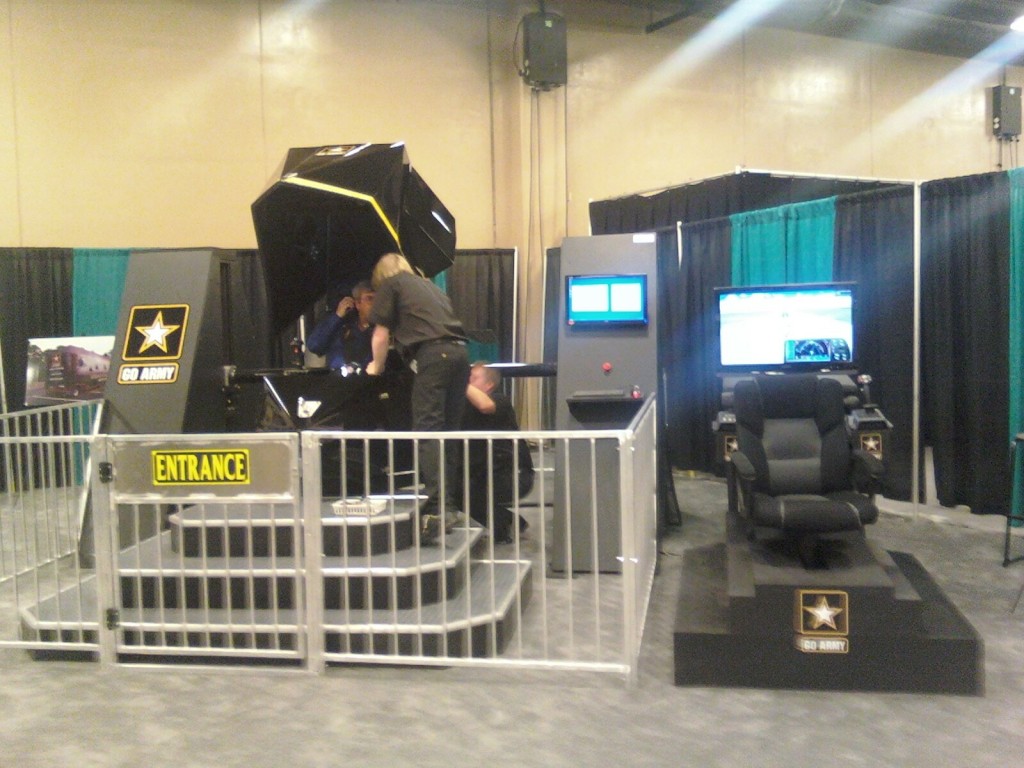
In September of 2010 I created a proposal detailing the system that we would create that would link the motion based platform to the Prepar3D simulation software. In addition, I proposed that we incorporate actual aircraft flight gauges to complete the illusion in the cockpit of actually flying a plane. The Army agreed with the proposal, and I managed the design and construction of the system along with the development of the system software. The final system was demonstrated at the Army Aviation Association of America in Nashville in April of 2011. It was a complete success. Here is a photo of the system as it was set up down at the show.
The Next Step
The project was ahead of schedule and well under budget. We had already demonstrated the system running against simulation software. After meeting with the customer, it was agreed that we would take it to the next level and attempt to integrate that system with an actual UAV. I contacted several UAV vendors and worked closely with Navmar on a conceptual design that would interface our ground station to their Mako UAV.
The key issue became not one of technical feasibility, we had a plan that would work, and it instead became one of cost and risk. Navmar had one UAV that they could use for this project The cost for a UAV is in the area of $250K. Should an issue arise during testing (i.e. we crash it) they could lose their one aircraft. In the end, the risk outweighed the reward, and we had no UAV platform to test against.
A DIY UAV
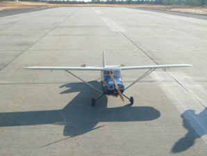
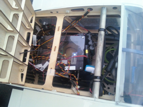
Unable to get an actual UAV to integrate and flight test against, we decided that we would take the more difficult route and construct our own “UAV” for testing out our motion ground station. Our UAV consisted of a giant scale gas powered RC plane equipped with a custom ARM based control system, a high definition video camera, and transmitters for both video and flight/control data. Here is a picture of the completed aircraft on the runway at Warren Grove Range and the flight control system inside it.
The Complete System
The following is an overview diagram of the complete system that was built.
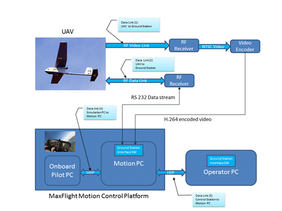
The sub-components that comprise the system are discussed below.
The Ground Station
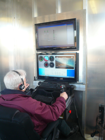
The ground control station consisted of a custom trailer which housed the MaxFlight motion system with the flight control sub-systems (multi-monitor display, aircraft flight controls, etc.) and an operator station. The operator station provided multiple additional capabilities to the overall system. The console had the capability of monitoring the flight gauges, presented the operator with the video display, and provided full flight controls. With these capabilities it provided a redundant point of flight control as it was capable of assuming control of the aircraft. It also could serve as a training station for new pilots. Here is a picture of the operator console in use during a flight test.
The following is a diagram of the individual hardware components that were used to create the control and flight data link as well as the video down link and encoder.

Video Transmission Link
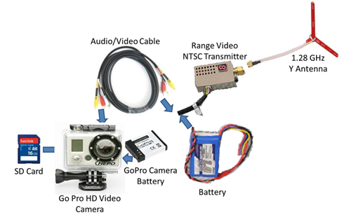
The video transmission link from the aircraft to the ground station consisted of the following commercial components. The video transmitter was a standard definition NTSC transmitter. The camera onboard the aircraft was capable of HD video output. Due to cost constraints the lower resolution NTSC transmitter was used. All flight video data was recorded onboard the aircraft to a SD card in high definition (1080p). Here are the components that comprised that subsystem.
Flight Control System
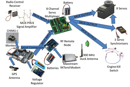
The flight control system was very close to that of an actual UAV. The aircraft was capable of being controlled by a standard RC flight controller, or by an ARM based on-board flight control system running our custom flight control software. Control of the aircraft could be passed back and forth between the motion-controlled ground station and the RC flight controller by the flick of a switch located on the RC controller. In addition, the on-board controller listened for a “heart beat” packet to be sent from the ground station. Upon loss of this heart beat packet or RF control signal the system was equipped with a kill switch that would cut off the engine. This was a safety feature which we added to insure that the aircraft did not stray off into commercial airspace should we lose control of it.
Here are the flight control system components.
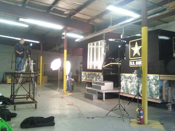
The system was assembled and there were several test runs performed in the parking lot prior to the actual flight test. Once we were satisfied that the system was operational, we took it down to Warren Grove Range and performed a flight test. A video production company was hired to create a promotional video that was used at the Army Aviation Association of America show in Nashville in 2011. Here is a picture of a photo shoot session we did prior to taking the system for the flight test.
The flight test at the range went great! There were several minor issues, such as the orientation of the roll pitch indicator was revered, etc. But overall it was a tremendous success. I’d like to extend my personal thanks to my entire engineering team that you see pictured at the top of this post. They made this project a success. I’ve never worked with a better group of professionals.
Below is the promotional video that we made for the show. It shows the pilot in the motion simulator flying the plane on the left, the view of the aircraft from the ground in the upper right and the view from the cockpit inside the simulator on the lower left.
